Friday, July 24, 2009

014 Window Wheel Mechanism - Part #3

The Second Hinge

This video tutorial shows the modeling of the second hinge part using Pro/E. There are four videos. The first two videos show the modeling of the punches used in the modeling of the hinge, while the last two show the modeling of the hinge itself. The punch tools are used to make the forms or the protrusions in the hinge.

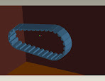
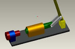
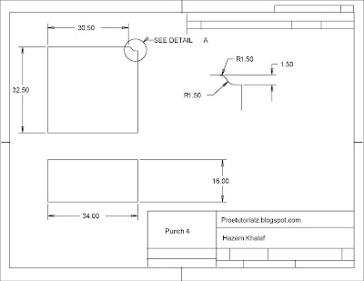
The punches are modeled using the normal part module while the hinge is modeled using the sheet metal module. Shown in the images below are the detailed drawings of the two punches and the hinge. The real image of the hinge is shown in this tutorial: 012 Window Wheel Mechanism - Part #1


The modeling of this Hinge is done in simple 5 steps:

  1. First, the two punch tools are created by using the revolve and extrude tool and this is shown in the first two videos.
  2. The side wall of the Hinge is created using the sheet metal module.
  3. The other two walls surrounding the base are created at the edges of the base using the profile shown in the above detailed drawing.
  4. The punch forms are applied using the form feature.
  5. Some dimensions are missing and are assumed during modeling since this is not going to affect our modeling later on.


Here are the four Pro/E video tutorials showing the modeling of this Hinge:


Friday, July 17, 2009

013 Window Wheel Mechanism - Part #2

The First Hinge

This video tutorial shows the modeling of the first hinge part using Pro/E. First, there will be a video to create the punch tool and then there will be another one to create the hinge itself. That punch tool will be used to make the form or the protrusion that is in the base of the hinge.

The punch is modeled using the normal part module while the hinge is modeled using the sheet metal module. Shown in the images below are the detailed drawings of the punch and the hinge. The real image of the hinge is shown in this tutorial: 012 Window Wheel Mechanism - Part #1


The modeling of this Hinge is done in simple 5 steps:
  1. First, the punch tool is created by using the revolve tool and this is shown in the first video.
  2. The Base of the Hinge is created using the sheet metal module.
  3. The two walls surrounding the base are created at the edges of the base using the profile shown in the above detailed drawing.
  4. The punch form is applied using the form feature.
  5. Some dimensions are missing and are assumed during modeling since this is not going to affect our modeling later on.

Here are the three Pro/E video tutorials showing the modeling of this Hinge:


Tuesday, July 7, 2009

012 Window Wheel Mechanism - Part #1


In this video tutorial, a Window accessory is modeled and assembled using Pro/E. It is mainly composed of sheet metal having a thickness of 1.5 mm. It has a small wheel moving forward and backwards. Actually, this tutorial is a kind of reverse engineering tutorial because I got this window accessory, disassembled it and modeled it. In this tutorial, several sheet metal techniques are introduced. So I hope this could be of benefit for those who are interested in sheet metal modeling. This mechanism is long and is, thus, divided into several parts. Today, we will start with part #1. Shown below are the pictures of the main window accessory (assembled) and each part separately is also shown.


Main window wheel Accessory


Main window wheel Accessory (2nd view)


Outer Container


Outer Container (2nd view)


First Hinge Part


First Hinge Part (2nd view)


Second Hinge Part

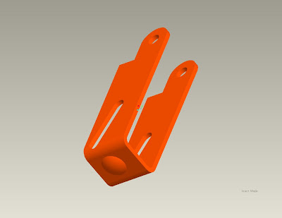
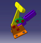
Second Hinge Part (2nd view)

Detailed Drawing of the wheel part

This wheel is modeled using two simple steps:

  1. The main cross section of the wheel is modeled and then revolved about the inner axis.
  2. The inner groove of the wheel is sketched on the perpindicular plane and then revolved.

Here is the video that shows the modeling of this wheel using Pro/E:


Thursday, July 2, 2009

011 Mechanical Belt Modeling

This tutorial shows the modeling of a mechancial belt like the one shown below. The tooth profile is shown in the picture below.


To model this Mechanical Belt, four steps are done:

  1. The tooth profile is drawn according to the dimensions shown above.
  2. The Profile is extruded.
  3. The extrusion is patterned using curve pattern technique.
  4. The curve of the pattern is drawn.


Here is the video that demonstrates the modeling of the belt:


Sunday, June 21, 2009

010 Nutcracker Modelling & Assembly - Part #9

The Assembly:


In this tutorial, we will be assembling all the parts that we have been modeling and creating using Proe since the tutorial "Nutcracker Modelling & Assembly **5** - part #1" until the tutorial "Nutcracker Modelling & Assembly **5** - part #8". So kindly, before you proceed in this tutorial make sure that you have created all the parts and that you followed all the videos in these tutorials to model all the parts correctly. The final assembly will be shown in the following figure and clip:


Here are the steps of the assembly:


  1. The Base is entered and mated with all the datums of the work screen.

  2. The Cylinder is entered is and mated with the base using its bottom surface and two diagonal holes.

  3. The Adjuster base is entered using the same technique used in step 2.

  4. The Adjuster is entered as a cylinder connection since it has two degrees of freedom (rotation and translation); its axis is aligned with the axis of the adjuster base and the lower surface of the adjuster is mated with surface of the adjuster base.

  5. The Hinge is entered, also using the same technique used in step 2.

  6. The Piston is entered as a cylinder connection since it has two degrees of freedom (rotation and translation); its axis is aligned with the axis of the cylinder.

  7. The Handle is entered as a pin joint since it has only one degree of freedom (only rotation); its lower pin hole is joined with the hinge hole using the align option.

  8. The Connection is entered using two sets of connections; a pin joint for the hole that is connected with the handle and a cylinder joint for the hole that is connected with the piston.


The video for this tutorial is splitted into two parts due to its size :


Thursday, June 18, 2009

009 Nutcracker Modelling & Assembly - Part #8

This tutorial shows the modelling of the Piston (No. 8). Its drawing is shown in the image below.


To model the the Piston, three steps will be done:
  1. The cross section of the cylinder with the groove will be drawn and revolved.
  2. The square part will be drawn on top of the cylinder and extruded.
  3. The small hole is placed at the surface of the part.

Here is the video that demonstrates the modeling of the Piston:

008 Nutcracker Modelling & Assembly - Part #7

This tutorial shows the modelling of the Hinge (No. 7). Its drawing is shown in the image below.


To model the the Hinge, three steps will be done:
  1. The main cross section will be drawn and extruded.
  2. The through hole will be drawn and extruded through both webs.
  3. The two small holes are placed at the buttom of the part.

Here is the video that demonstrates the modeling of the Hinge:


007 Nutcracker Modelling & Assembly - Part #6

This tutorial shows the modelling of the Handle (No. 6). Its drawing is shown in the image below.


To model the the Handle, three steps will be done:
  1. The main cross section of the square part will be drawn and extruded.
  2. The two small holes are placed at the surface of the extruded part.
  3. The cylindrical hand will be drawn and extruded at the end surface of the first part.

Here is the video that demonstrates the modeling of the Handle:

006 Nutcracker Modelling & Assembly - Part #5

This tutorial shows the modelling of the Connection(No. 4). Its drawing is shown in the image below.


To model the the Connection, two steps will be done:
  1. The main cross section, with the two through holes, will be drawn.
  2. The section will be extruded.

Here is the video that demonstrates the modeling of the Connection:

005 Nutcracker Modelling & Assembly - Part #4

This tutorial shows the modelling of the base (No. 3). Its drawing is shown in the image below.


To model the the Base, two steps will be done:
  1. The main cross section (the rectangle) will be drawn and extruded.
  2. The eight holes are placed at the surface of the part.

Here is the video that demonstrates the modeling of the Base:


Wednesday, June 17, 2009

004 Nutcracker Modelling & Assembly - Part #3

This tutorial shows the modelling of the cylinder (No. 5). Its drawing is shown in the image below.


To model the the Cylinder, two steps will be done:
  1. The main cross section with the through hole will be drawn and extruded.
  2. The four small holes are placed at the buttom of the part.

Here is the video that demonstrates the modeling of the Cylinder:


003 Nutcracker Modelling & Assembly - Part #2

This tutorial starts by modelling of the adjuster (No. 2). Its drawing is shown in the image below.


To model the adjuster, two steps will be done:

  1. The upper half of the cross section of the adjuster is drawn.
  2. This half is revolved around the center of the adjuster.

Here is the video that demonstrates the modeling of the Adjuster :


Tuesday, June 16, 2009

002 Nutcracker Modelling & Assembly - Part #1

This tutorial handles the modeling and assembly of a nutcracker that is shown above. The modeling of each part is in a separate tutorial and the assembly of the whole device is in another tutorial. Throughout the modeling of the parts, kindly follow the exact datum planes on which the sketching is done to ease the assembly part. This tutorial starts by modelling of the adjuster base (No. 1). Its drawing is shown in the image below.


To model the the Adjuster Base, two steps will be done:

  1. The main cross section with the through hole will be drawn and extruded.
  2. The two small holes are placed at the buttom of the part.

Here is the video that demonstrates the modeling of the Adjuster Base:

Monday, June 15, 2009

001 Let's Learn Pro/E

This blog is intended to be a learning community for Pro/E for both amateurs and professionals. This blog is a tutorial oriented blog where learning will be through both videos and explanatory snap shots. Your participations are highly appreciated through asking questions and providing feedback about the tutorials in the comment box.

Some of the tutorials in this blog are based on tutorials explained in books and on the web but handled in a more detailed manner while some others are created uniquely by us. The level of difficulty of these tutorials varies from a beginner level up to a professional level.

I hope that all readers and followers of this blog get the most benefit possible.

Best Regards,
Chief Editor,